
I. Purpose and scope of use
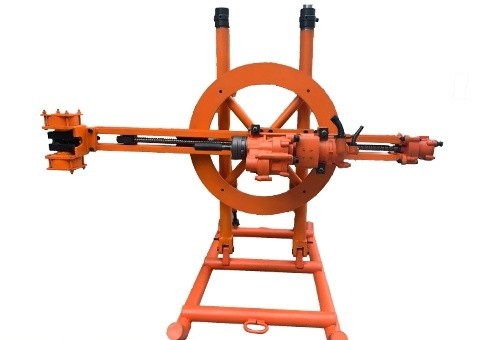
The type YGZ90 guide rail independent rotary rock drill can be used with rock drilling rigs or rock drilling benches. It can be used to drill medium-hard or hard rock (f = 8~18) andφ50~φ 80 mm blast hole. The effective hole depth can reach 30 meters horizontally.
FIG. 1 Outline
The machine is mainly used for drilling upward, parallel or fan-shaped holes in underground mining drilling. It can be used with open-pit drilling rig to drill down or horizontal holes in medium and small open-pit quarries or quarrying works. It can also be used in other operations that require drilling medium and deep holes.
II. Main technical specifications
Dimensions (length * width * height) | 876*355*303 mm |
Machine weight | 95 Kg |
Diameter of gas pipeline | 125 mm |
Piston weight | 7 Kg |
The working pressure is 0.63mpa | |
Impact energy | ≥225 J |
Drilling impact frequency | ≥34 Hz |
Working water pressure | 0.4~0.5 Mpa |
Brazing torque | ≥140 Nm |
Drilling gas consumption | ≤225 L/s |
Inner diameter of gas pipeline | |
Impact part | 38 mm |
Brazing part | 25 mm |
Inner diameter of water pipeline | 19 mm |
Hole diameter | 50~80 mm |
Drill tail specifications | 38×97 mm |
YGZ90 guide rail independent rotary rock drill
FIG. 2 Structure
Parts list of the type YGZ90 guide rail independent rotary rock drill
Model | Name | Quantity | Model | Name | Quantity |
-3 | Water needle gasket | 1 | -35 | Wind motor cover | 1 |
-4 | Intake-air screw | 1 | -39 | Pipe nut | 1 |
-5 | Water needle | 1 | -40 | Flange plate | 1 |
-6 | Long screw nut | 2 | -41 | Hose connector | 1 |
-7 | Long screw | 2 | -43 | Drill tail | 1 |
-8 | Gas distribution | 1 | -58 | Leather pad | 1 |
-10 | Spring | 1 | 25-01 | Butterfly nut | 2 |
-12 | Cylinder block | 1 | 25-4 | Tapered hose connector | 2 |
-13 | Connector | 1 | 305 | Single row radial ball bearing | 4 |
-14 | Copper sleeve | 1 | 4644104 | Needle roller bearing | 2 |
-15 | Bushing | 1 | 4644107 | Needle roller bearing | 2 |
-16 | Rotating sleeve | 1 | YG80-1 | Waterproof cover | 1 |
-17 | Gasket ring | 1 | YG80-27 | Gasket ring | 1 |
-18 | Drill tail sleeve | 1 | YG80-36 | Gas pipeline elbow | 1 |
-19 | Sealing ring | 1 | YG80-37 | Gas pipeline nut | 1 |
-21 | Nose cover | 1 | YG80-38 | Snap ring | 1 |
-23 | Guide sleeve | 1 | YG90-1 | Handle body | 1 |
-24 | Pinch sleeve | 1 | YG90-9 | Valve stem | 1 |
-25 | Spring circlip | 1 | YG90-11 | Piston | 1 |
-26 | Connector nut | 1 | YG90-20 | Nose | 1 |
-28 | Elbow connector | 1 | YG90-22 | Mechanism set | 1 |
-29 | Retaining ring | 1 | YG90-26 | Mandrel | 1 |
-29 | Anti-loose nut | 3 | YG90-27 | Gear | 1 |
-31 | Wind motor | 1 | YG90-28 | Shaft gear | 1 |
-33 | Gear | 1 | YG90-30 | Gear | 1 |
-34 | Pin shaft | 1 | YG90-32 | Spacer | 1 |
YG90-37 | Air duct connector | 2 | 8*28GB1099-72 | Semi-element bond | 1 |
YG90-38 | Double gear | 1 | 30*3.1GB1235-76 | O-ring seal | 2 |
YG90-39 | Cover plate | 1 | 40*3. 1GB1235-76 | O-ring seal | 1 |
YG90-40 | Exhaust hood | 1 | 45*3.1GB1235-76 | O-ring seal | 1 |
YG90-41 | Meta pin | 4 | 65*3.1GB1235-76 | O-ring seal | 1 |
12GB854-67 | Single lug return washer | 4 | M6GB45-66 | Hexagon nut | 4 |
12GB859-66 | Spring washer | 5 | M6*16GB67-66 | Half head screw | 4 |
16GB859-66 | Spring washer | 1 | M12*16GB30-66 | Hexagon head nut | 4 |
22GB893-67 | Circlip for hole | 1 | M12*30GB21-66 | Small hexagon head bolt | 6 |
26GB893-67 | Circlip for hole | 1 | M16*80GB21-66 | Small hexagon head bolt | 2 |
62GB893-67 | Circlip for hole | 1 | M16*100GB21-66 | Small hexagon head bolt | 1 |
68GB893-67 | Circlip for hole | 1 | M16*180GB21-66 | Small hexagon head bolt | 1 |
6jc*25GB119-66 | Meta pin | 2 |
III. Structural features and working principle:
(I) Structural features:
The independent structure of impact and rotary drill is adopted in YG90 drill (see Figure 2). The impact energy and the rotational speed of the drill rod can be adjusted according to the conditions of ore and rock. The impact part adopts valveless air distribution, which can make good use of the expansion of compressed air for work. The rotary bit is driven by a geared air motor, and the rod is driven to rotate by a two-stage spur gear. Geared air motors are placed on the upper part of the drill to shorten the overall length of the drill, which is better suited for narrow down-hole operations.
(II) Working principle:
1. Impact part:
When the impact part of the control valve is opened, the compressed air through the air duct into the handle body chamber (1) (see Figure 3), the valve rod at the tail of the piston alternately into the compressed air into the front or back chamber of the cylinder, so as to push the piston for high-speed reciprocating motion, constantly hitting the drill tail.
(1)
Piston stroke action:
a. When the piston is in the position shown in FIG. 3a, the compressed air enters the rear chamber of the cylinder through the air inlet (2) of the rear chamber through the neck of the piston valve rod, thus accelerating the piston. At this time, the air front cavity (5) is communicated with the atmosphere, and the remaining gas in the front cavity (5) is discharged into the atmosphere through the exhaust port (4).
Figure 3. a
b. When the piston advances to the position shown in FIG. 3 b, the leading edge of the valve gas distribution (6) closes the air inlet (2) of the back chamber to stop the air intake, and the pressure gas in the back chamber (3) begins to expand to do work, thus pushing the piston forward.
Figure 3. b
c.
The piston continues and then closes the exhaust port. The anterior chamber (5) becomes a closed chamber in which the gas is compressed (FIG. 3 b). At this time, the gas in the back chamber (3) continues to expand to do work, and pushes the piston forward until the exhaust port is opened.
FIG. 3 c
d. When the piston is about to open the exhaust port, the trailing edge of the piston valve gas distribution (7) opens the inlet direction of the front chamber, and the pressure enters the front chamber (5) (as shown in FIG. 3 d). When the piston opens the exhaust port, the back cavity (3) is communicated with the atmosphere, and the remaining gas is discharged into the atmosphere by the exhaust port (4). The piston relies on inertia to overcome the resistance of compressed air in the front cavity and slide forward to hit the drill tail, thus completing the stroke action.
FIG. 3 d
(2) Return action of the piston:
e. After the piston opens the drill tail, it accelerates back due to the thrust of the compressed gas and the reaction force of the drill tail. The trailing edge of the piston valve rod (7) closes the air inlet of the front chamber (8), stops the air intake, and the compressed air in the front chamber (5) begins to expand (as shown in FIG. 3 e).
FIG. 3 e
e. The piston continues to move backward and closes the exhaust port (4). The back chamber becomes a closed gas chamber, the gas in the back chamber (3) is compressed, and the compressed gas in the front chamber (5) continues to expand until the exhaust port is opened (see FIG. 3 f).
FIG. 3 f
g. The piston continues to move backward, while the leading edge of the piston valve gas distribution opens the rear chamber air inlet. The pressure gas enters the back chamber (3), and the pressure in the back chamber rises rapidly, impeding the backward movement of the piston. Almost at the same time, the piston opens the exhaust port, and the remaining gas in the front chamber (5), which reduces the pressure due to expansion, escapes from the exhaust port (4) (FIG. 3 g). The piston relies on inertia to overcome the resistance to move backward, and the speed decreases rapidly. When the speed reaches zero, the return action is complete and the next cycle of stroke action begins.
FIG. 3 g
(3) The role of the starting valve:
The pistons of valveless distribution are sometimes in dead point position (FIG. 4). At this point, the front and rear cavity air intakes and exhaust ports are closed by the piston, can not be started.
For this purpose, a starting valve (1) is set in the distribution gas.
When the impact part of the control valve is opened, the air pressure through the hole (3) into the rear chamber of the cylinder, push the piston forward, leaving the dead point position, so as to complete the starting action.
Subsequently, due to the size of the front and back ends of the stem (1) and the pressure difference caused by the stem to overcome the resistance of the spring (2) quickly moved forward. Close the hole (3). The hole (3) is always closed when the impact is working normally.
When the impact part of the control valve is closed to stop the impact, the pressure difference between the two ends of the valve stem then disappear, the valve stem is pushed back to the original position by spring (2), and ready for the next start.
FIG. 4
2. Rotating part:
The rotating part is driven by a gear-type wind motor. Please see (Figure 5) for the specific working principle. When the control valve of the rotating part sends the compressed air into the wind motor from the right air duct, and the left air duct is in communication with the atmosphere, the compressed air generates a pressure difference on the gear of the wind motor, so that the gear rotates in the direction shown in the figure. The compressed air is filled in the tooth groove and flows into the left side of the wind motor along the direction of the gear rotation, and escapes into the atmosphere through the left air duct. Conversely, if the compressed air is sent into the wind
FIG.五
motor from the left air duct and the right air duct is in communication with the atmosphere, the wind motor gear rotates in the opposite direction. When the wind motor gear (YG90-38) is connected with the driving gear (see Figure 2) to rotate, the gear YG90-30, the shaft gear YG90-28, the gear YG90-27, and the rotating sleeve YG90-16 are driven. When rotating, the rotating sleeve drives the pinch sleeve YG90-24 with its jaw-like clutch, and the pinch sleeve cooperates with the drill tail of the shank YG90-43 with its flat hole to drive the shank to rotate.
Since the gear-type wind motor can rotate in both forward and reverse directions, the shank tail can also be forward and reverse, which is convenient for connecting and disassembling the drill rod.
IV. Use, maintenance and technical security
(I) Use
Because the rotating torque of the YG90 rock drill is relatively large, it is not easy to stick during the process of drilling the ore rock with cracks and caves. Even if the sticking failure occurs sometimes, the weak impact and strong rotation method can be used to eliminate the fault. The optimal shaft thrust range adapted to the rock drill is large, so it is easy to operate.
The operation essentials are briefly described as follows:
1. For rock with different lithology, the impact energy, drilling speed and axial thrust should be adjusted respectively according to the discharge condition to obtain higher drilling speed. For hard rock, the impact energy can be smaller, drilling speed can be higher, the axial thrust should not be too large, and for hard rock, the impact energy can be larger, the drilling speed can be lower and the axial thrust should be larger.
2. In case of cracks and caves, when the brazing occurs, it is necessary to reduce the impact energy, increase the drilling speed, and even stop the impact, completely rely on rotary to pass the brazing area to troubleshoot.
3. Because it is valveless air distribution, it is appropriate to work under high pressure, and the working pressure is not less than 5 kg/cm2.
4. The washing water pressure should not be less than 4kg/cm2.
5. The lubrication condition of rock drill should be good to prevent the friction surface (especially the matching surface of piston, cylinder and gas distribution) from local high temperature and damage when moving at high speed.
The lubricating oil can be determined according to the temperature of the working environment, whether it is No. 30 engine oil or No. 20 engine oil.
Lubricating oil should be continuously supplied. Under normal circumstances, the oil injector can be used to adjust the oil supply. The oil supply should be controlled in each working class to consume 3~5 kg. Too much will cause oil mist, too little is poor lubrication.
6. The drilling tools used should meet the quality requirements.
(II) Maintenance:
1. Regularly check and repair the rock drill, pay attention to observe the wear of each part, and repair or replace the missing parts in time to avoid damage to other parts.
2. Before each operation, the oil should be filled with oil, all the fastening screws should be carefully checked to ensure the reliability of the connection, and then the rock drill should be run dry with a small wind to check whether the machine is running normally, and at the same time make the machine lubricated.
3. After the operation is completed, close the water valve and let the rock drill run idling for a short time with a small wind to remove the accumulated water to prevent corrosion.
4. If the rock drill is not to be used for a long time, it must be removed and washed in time, coated with anti-rust grease, and stored in a dry place.
(III) Technical security:
1. Before use, it is necessary to blow off the dirt in the air duct. All the fastening screws must be evenly tightened and the fastening conditions must be observed frequently to prevent loosening.
2. Never drive an empty car with full wind.
3. When the impact part does not start well, the control valve needs to be shut down, and then start again after the remaining air in the air duct is discharged. It is strictly forbidden to knock the cylinder to prevent the cylinder from deforming.
4. The pipe connections must be firm to prevent accidents from falling off.
V. Precautions for disassembly and assembly
(I) In disassembly and assembly, do not use hammer to hit the matching surface of each part. Use copper rods or hardwood pads to prevent damage to parts.
(II) Under the normal circumstances, the cylinder and the coupling body should not be separated.
(III) The wind motor should not be disassembled at will except when the wind motor is regularly repaired and confirmed to be faulty.
(IV) When replacing the copper sleeve, it is not appropriate to directly hit the copper sleeve to avoid deformation. The copper sleeve can be put on the piston, and the piston is loaded into the cylinder (at this time the cylinder and the connecting body are mounted together) with lubricating oil on the mating surface. Copper or hardwood pads are placed at the end of the piston and pressed in with a press or hammered in with a hammer. After the copper sleeve is set, pull the piston by hand and see if it is well matched. If the resistance is large, the scraper is used to scrape the inner hole of the copper sleeve carefully.
(V) When assembling, all mating surfaces should be scrubbed clean and coated with lubricating oil.
(VI) All fastening screws should be tightened evenly.
VI. Common faults and troubleshooting methods
Serial number | Phenomenon | Reason | Troubleshooting method |
1 | The sound of the machine is abnormal. | The tightening screws are loose or the tightening force is uneven. Pistons, cylinders, etc. are slightly scratched. | Tighten the fastening screws evenly. If this phenomenon cannot be ruled out, it should be disassembled and repaired. |
2 | The movement of the piston is abnormal (sometimes impact, sometimes not impact). | The piston and the cylinder or the matched gas are scratched, and the tension of the long screw is uneven. | Disassemble the piston, carefully polish the scratched part with a whetstone and properly adjust the tension force. |
3 | The drill tail does not rotate and the wind motor runs normally. | The end teeth of pinch sleeve or rotating sleeve are broken. Bearing is damaged or gear tooth is damaged. | Replace damaged parts. |
4 | Serious icing occurs at backwater and exhaust port. | Water needle or the drill tail seal ring damage, too much water in the compressed air. | Replace the damaged parts and reduce the moisture in the compressed air. |
5 | The rock drilling speed is reduced. | The length of brazing tail is not qualified, and there are too many depressions on piston end face. | Replace the drill tail and piston. |
E-mail:[email protected]
Tel.:+86-316-8800560
Address:No.189 Qukou Town, Xianghe County, Langfang City, Hebei Province,China